Assembly
This page isn’t quite complete yet! I’m still waiting for the LED PCBs and some screws to arrive before I can take better pictures and update the instructions. Regardless, the current state should help you get a good impression of what steps are necessary to assemble a freetserv.
Soldering and crimping
There are plenty of SMD soldering instructions discoverable on the internet, so I’m not going to repeat what you can learn from them. For example, CuriousInventor’s Surface Mount Soldering 101 is a great video illustrating how to solder various parts of various sizes.
Populate the freetserv PCBs
This step will take about 3 to 4 hours per PCB,
so plan for two full days of work.
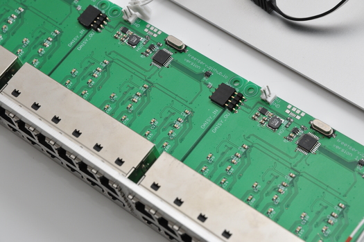
Start with the bottom side containing the FT4232 ICs. These are the ICs which have the smallest and the most pins, so after you have successfully soldered them on, it’s only going to get easier.
This step has the highest part diversity, so neatly arrange the parts you are going to need. Finish the area around and on top of the FT4232 ICs by soldering each part on all three instances.
Solder the remaining twelve MAX3232 ICs and their four 0.1μF capacitors each.
Turn the board around and solder the parts from most complicated to easiest:
- ICs with tiny pins or many pins
(e.g. MCP16311, TUSB2046BVF) - hard-to-reach capacitors and resistors
- all remaining surface-mount devices (SMD)
- all remaining through-hole devices
(e.g. the 8P8C ports)
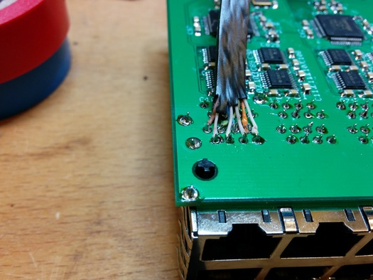
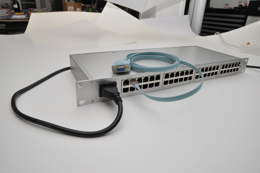
Connect the ethernet extension
Issue #26 tracks adding a pin header for the ethernet extension, which is a cleaner and simpler alternative than what’s currently described here. If you want to help, consider working on issue #26.
Cut open an ethernet cable and strip the isolation off of the individual wires.
The cable I have used seems to have come with a non-standard wiring, so I don’t have a good pin-out handy — sorry! You’ll need to use a multimeter to see which pin needs to be connected where.
Populate the LED module
Solder the LEDs onto the PCB.
For each of the two LEDs, solder the 3.3kΩ resistor to one of the LED’s pins (doesn’t matter which one), possibly cutting the pins of both the LED and the resistor beforehand to make the entire construction less bulky.
Solder a cable to the other LED pin and to the resistor. Leave the cables unconnected for now, they will be used in the step “Crimp Raspberry Pi connector”.
Isolate the construction using heat shrink tube.
Crimp mains power cable
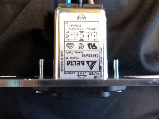
For safety reasons, you must not solder wires that transfer 230V, as the solder could get hot enough to unsolder itself. Hence, the power supply uses JST terminals, and on the power filter, we are using TE AMP quick connectors (Digi-Key A27817CT-ND).
Cut the power cable to an appropriate length.
Crimp one JST SVH-41T-P1.1 (Digi-Key 455-1319-1-ND) terminal onto each wire of the power cable. Then insert the terminals into the JST VHR-5N (Digi-Key 455-1186-ND) housing.
As described in a parallax forum post, with the Molex 63811-1000 (Digi-Key WM9999-ND), you can achieve an acceptable crimp. The “3.2mm insulation” slot of the Molex tool worked best for me.
On the other end of the cable, which connects to the power filter, use the same Molex 63811-1000 (Digi-Key WM9999-ND) to crimp one TE AMP quick connector (Digi-Key A27817CT-ND) onto each wire.
TODO: update for grounding the case using A119654-ND + 3 H767-ND washers underneath the PSUCrimp cable for the fan
Crimp Raspberry Pi connector (board, led module, psu)
Putting it all together
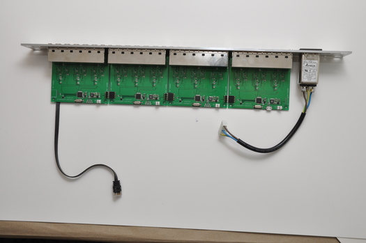
Mount the PCBs in the front plate
Start by pushing each single PCB individually into its corresponding front plate cutout. What worked well for me is to first insert the PCB with a slight angle, so that the 8P8C ports are touching the front plate cutout at the top and bottom. That holds the board in place pretty well, and then you can push the board into the cutout with a bit more force.
After doing this once, it will be easier to insert the PCB afterwards, so you will have an easier time when inserting all 4 of them together (they are daisy-chained, so they need to be inserted together).
To insert all PCBs, start by inserting the first one so that the 8P8C ports touch the front plate cutout at the top and bottom. Then, connect the next PCB’s daisy-chaining connector and also make its ports touch the cutout top/bottom. Repeat for the remaining two PCBs. You will have enough wiggle room to now correctly align the PCBs and push them into the front plate. In the next step, we will properly fasten them, finishing the alignment/insertion process.
Install the power filter
Use two 16mm M3 screws (Digi-Key 36-29316-ND) with two M3 hex nuts (Digi-Key 36-4708-ND) to fasten the power filter in the front plate.
TODO: update for better screws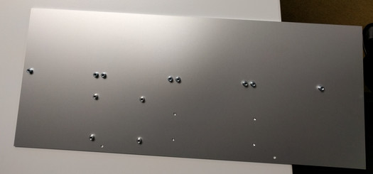
Put bottom plate into front plate, screw in PCBs
The bottom plate is the only plate with threaded standoffs. Insert it into the front plate so that the 8 threaded standoffs for the PCBs are underneath the corresponding holes in the PCBs.
Use the 4mm M3 Phillips screws (Digi-Key 335-1150-ND) to fasten the PCBs. Don’t screw them in too tight yet — we’ll properly tighten them once the side profile and back plate are fastened.
Install the LED board
Use two 4mm M3 Phillips screws (Digi-Key 335-1150-ND) with one M3 flat washer (Digi-Key H767-ND) each to fasten the LED PCB. Since the board is symmetrical, pay attention that you plug it in the correct way around, i.e. matching the front plate LED labels.
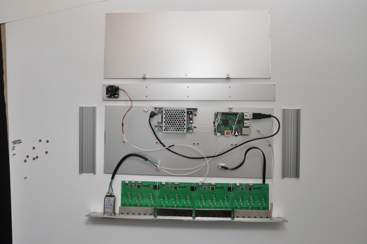
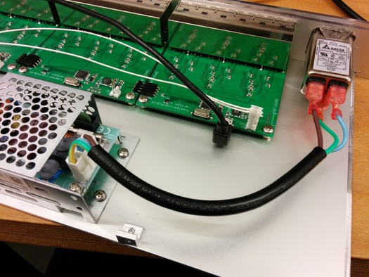
Install power supply and Raspberry Pi 2
Use the 4mm M3 Phillips screws (Digi-Key 335-1150-ND) to fasten the power supply as illustrated in the picture on the left.
Use the M2.5 screws (Digi-Key 36-29300-ND) to fasten the Raspberry Pi 2.
Use a short USB-A to USB-micro-B cable, e.g. this 0.5m right-angled USB-A to USB-micro-B (Digi-Key 1175-1694-ND) cable, to connect the first freetserv PCB’s “HOST” port to any of the Raspberry Pi 2’s USB ports.
Connect the ethernet extension cable to the Raspberry Pi 2’s ethernet port.
Connect the Raspberry Pi connector module to the power supply and the freetserv PCB’s power connector.
TODO: highlight this in the picture
TODO: connect PSU→rpi2 TODO: connect rpi2 connector→[5V freetserv, led module] TODO: connect freetserv→led module
Install the fan
Use four 16mm M3 screws (Digi-Key 36-29316-ND) with four M3 hex nuts (Digi-Key 36-4708-ND) to fasten the fan in the back plate.
TODO: better picture
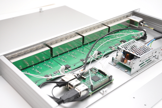
Assemble case, tighten screws
Use the screws of the Schaeffer AG Montageset to screw the side profiles to the front plate, and to screw the back plate to the side profiles. Do not slide in the top plate just yet, so that you still have access to all components for the next step:
Since all components are now in their final position, tighten all 4mm M3 Phillips (Digi-Key 335-1150-ND) and M2.5 screws (Digi-Key 36-29300-ND).
Functional testing
Now is a good time to perform functional tests if you haven’t already. Verify the following checklist:
- The power LED lights up as soon as you connect mains power.
- The watchdog LED blinks every other second as soon as the Raspberry Pi booted. See Software setup if you haven’t installed the Raspberry Pi yet.
- You can establish an ethernet link when connecting to the
eth0port. - When logging into the Raspberry Pi,
/dev/ttyUSB0to/dev/ttyUSB47are present. - In the
dmesgoutput, there are no USB errors. NOTE: issue https://github.com/freetserv/freetserv/issues/34 - The fan spins and blows air out of the case.
Assemble case with top plate
Unscrew and remove the back plate again.
Screw the Schaeffer AG case brackets into the bottom and top plate.
Slide in the top plate.
Screw the back plate to the side profiles, screw all case brackets.